Front Suspension (page 4)
 30-12 Shock absorber Removal and Installation 30-12 Shock absorber Removal and Installation
a. Removal (Kadett)
1. Remove plastic cover over shock absorber upper attachment.
2. Raise car and support with stands.
3. Remove upper attaching nuts from shock absorber.
4. Remove lower attaching nut, lock-washer and bolt.
5. Compress shock absorber and remove from car.
b. Removal (GT)
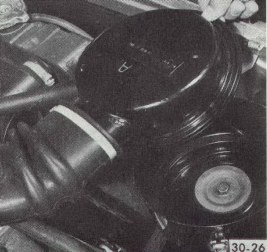
Figure 30-19 Air Cleaner Removal
|
|
|
2. Remove plastic cover over shock absorber upper attachment.
3. Raise car and support with stands.
4. Remove upper attaching nuts from shock absorber.
5. Remove lower attaching nut, lock-washer and bolt.
6. Compress shock absorber and remove from car.
c. Installation (Kadett)
1. Inspect shock absorber for damage and seal leaks. Always replace the upper and lower rubber grommets when replacing a shock absorber.
2. Install the lower grommet retainer and grommets on shock absorber. Compress shock absorber and place in position.
3. Install lower attaching bolt and nut. Torque to 30 lb. ft.
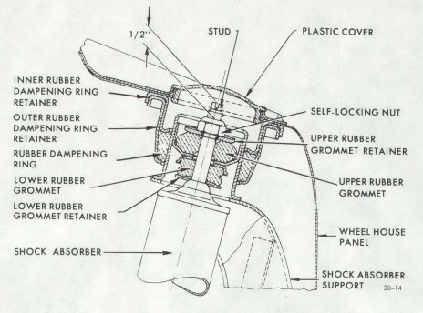
4. Install nuts on upper attaching studs. Tighten nuts until distance from top of nut to stud is approximately ½". See Figure 30-20.
5. Install plastic cover.
c. Installation (GT)
1. Inspect shock absorber for damage and seal leaks. Always replace the upper and lower rubber grommets when replacing a shock absorber.
2. Install the lower grommet retainer and grommets on shock absorber. Compress shock absorber and place in position.
3. Install lower attaching bolt and nut. Torque to 30 lb. ft.
4. Install nuts on upper attaching studs. Tighten nuts until distance from top of nut to stud is approximately ½". See Figure 30-20.
5. Install plastic cover.
6. Install air cleaner.
Figure 30-20 Shock Absorber Upper Attachment
|
|
|
30-13 FRONT SPRING REMOVAL AND INSTALLATION
a. Removal
1. Raise car and support at rear of front frame rails with stands.
2. Remove front wheels.
3. Remove cotter pin from castle nut on lower ball joint studs and back off castle nut two (2) turns. Hit ball stud with a sharp blow to break it loose. Do not remove nut.
4. Install J-21689 spring compressor and compress the spring until 3 1/8" clearance is obtained between spring and compressor.
5. Disconnect both shock absorbers at their lower attachment. Compress both shock absorbers.
6. Support the rail of J-21689 Spring Compressor with a jack. Remove the lower control arm to cross member attaching nuts and bolts.
7. Remove the lower ball joint stud nuts. Slightly lower jack so that the spring and lower control arm assembly is removed from the front cross member and steering knuckle.
8. Lower the jack, spring compressor, front spring and control arm assembly. Remove the lower control arm to spring nuts.
9. Relieve tension on spring compressor and remove control arm attaching bolts and control arms.
b. Installation
NOTE: Fasteners in subparagraphs b are important attaching parts in that they could affect the performance of vital components and systems, and/or could result in major repair expense. They must be replaced with one of the same part number or with an equivalent part if replacement becomes necessary. Do not use a replacement part or lesser quality or substitute design. Torque values must be used as specified during reassembly to assure proper retention of these parts.
1. Attach lower control arm to front spring eye. Torque bolts to 18 lb. ft.
2. Install spring compressor on spring and compress spring to appropriate length.
3. Raise jack with spring compressor, spring and control arm assembly into position under the car.
4. Install lower ball joints and torque nuts to 40 lb. ft. Install new cotter pin.
5. Attach lower control arms to frame cross member using new lock nuts.
6. Attach both shock absorbers. Torque bolts to 30 lb. ft.
7. Remove spring compressor.
8. Install front wheels.
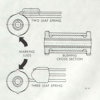
NOTE: On replacement of the damper bushings on the front springs, ensure that irrespective of two or three leaf spring, only the one-part damper bushing is installed.
Figure 30-21 Front Spring Damper Bushing
|
|
|
|