Front Suspension (page 3)
2. Install dust cap on lower ball joint and fill with chassis lubricant. Attach dust cap retainer.
3. Press ball joint into steering knuckle. Use J-9519-3 as installer and J-21690 as a supporting sleeve.
4. Install castle nut on ball joint stud and torque to 40 lb. Ft. Install new cotter pin.
5. Reconnect shock absorber to the lower control arm and torque to 30 lb. ft.
6. Remove spring compressor.
7. Install front wheels and lower the car.
8. Always check caster and camber after ball joint replacement.
 30-9 UPPER CONTOL ARM REMOVAL AND INSTALLATION 30-9 UPPER CONTOL ARM REMOVAL AND INSTALLATION
a. Removal
1. Raise car and support at rear of front frame rails.
2. Remove front wheel.
3. Install spring compressor and compress spring until there is 3 1/8" between compressor and lower spring leaf.
4. Remove cotter pin and castle nut from upper ball joint stud. Discard cotter pin.
5. Use tire rod remover J-21687 to remove ball joint from steering knuckle. See Figure 30-12.
6. Support brake drum to relieve tension on brake hose.
7. Remove hex nut from upper control arm shaft. Remove shaft and washers from shock absorber support.
NOTE: Do not damage threads on control arm shaft.
8. Remove control arm from car. Do not lose inner toothed washers. Note size and location of toothed washers.
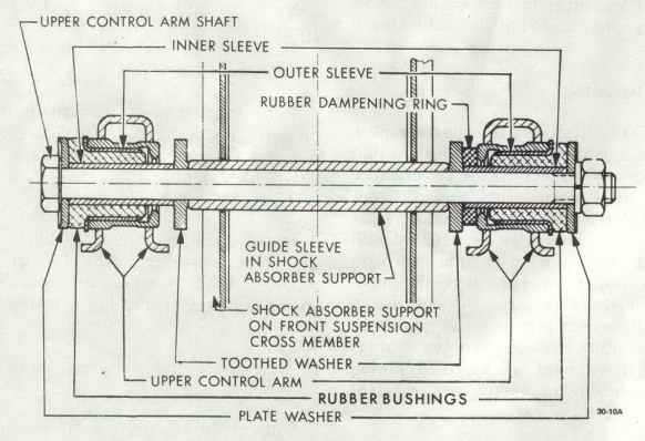
Figure 30-15 Upper Control Arm Shaft and Bushings
|
|
|
b. Installation
NOTE: If rubber bushings on control arms are worn, arms must be replaced.
1. Slide rubber rings over bushings. Slide rings over inner sleeves of bushings. Place control arm in position on shock absorber support. Installing toothed washers in their original positions. See Figure 30-15.
2. From front to rear, install control arm shaft. If necessary, align washers and control arm bushings with a small drift prior to installing control arm shaft. See Figure 30-15.
3. Tighten hex nut on control arm shaft finger tight.
4. Increase tension on spring compressor in order to relieve tension on control arm shaft. Then torque hex nut on control arm shaft to 33 lb. ft.
5. Press ball joint stud into steering knuckle and torque castle nut to 29 lb. ft. Install new cotter pin.
6. Remove spring compressor and lower car.
7. Check front-end alignment.
30-10 LOWER CONTROL ARM REMOVAL AND INSTALLATION
a. Removal
1. Raise car and support at rear of front frame rails.
2. Remove front wheel.
3. Remove cotter pin from castle nut on ball joint stud and back off castle nut two (2) turns. Hit ball stud with a sharp blow to break it loose. DO NOT REMOVE NUT.
4. Install spring compressor and compress spring until there is 3 1/8" between compressor and lower spring leaf.
5. Disconnect and compress shock absorber.
6. Support rail of spring compressor with a jack. REMOVE LOWER CONTROL ARM FROM FRAME CROSS MEMBER. Nuts may have to be removed with a punch. See Figure 30-16. Discard the lock nuts.
7. Remove lower ball joint stud nut. Slightly lower jack so that spring and lower control arm assembly is removed from the front cross member and steering knuckle.
8. Lower jack, spring compressor and front spring with control arm assembly. Remove lower control arm to spring nuts.
9. Release spring compressor and remove control arm attaching bolts and control arm.
Figure 30-16 Lower Control Arm Attachment
|
|
|
b. Installation
NOTE: Fasteners in subparagraphs b are important attaching parts in that they could affect the performance of vital components and systems, and/or could result in major repair expense. They must be replaced with one of the same part number or with an equivalent part if replacement becomes necessary. Do not use a replacement part or lesser quality or substitute design. Torque values must be used as specified during reassembly to assure proper retention of these parts.
1. Attach lower control arm to front spring eye. Torque bolts to 18 lb. ft.
2. Install spring compressor and with a jack raise spring compressor with spring and control arm assembly into position for pressing ball joint into steering knuckle.
3. Press ball joint into steering knuckle. Use J-9519-3 as installer and J-21690 as a supporting sleeve.
4. Install castle nut on ball joint stud and torque to 45 lb. ft. Install new cotter pin.
5. Attach lower control arm to frame cross member using new lock nuts.
6. Reconnect shock absorber to lower control arm and torque to 30 lb. ft.
7. Remove spring compressor.
8. Install front wheel and lower the car.
9. Check front-end alignment.
30-11 STEERING KNUCKLE REMOVAL AND INSTALLATION
a. Removal (Drum Brakes Only)
1. Raise car and support at rear of front frame rails.
2. Remove hub cap and spindle grease cap. Pull cotter pin and removal spindle nut and front wheel together with brake drum and hub.
3. Remove brake backing plate to steering knuckle attaching bolts.
4. Compress front spring with J-21689 spring compressor until 3 1/8" clearance is obtained between compressor and spring.
5. Remove cotter pin and castle nut from upper ball joint stud.
6. Using tie rod remover J-21687, press out upper ball joint.
7. Remove shock absorber at lower attachment only.
8. Remove the lower ball joint from steering knuckle using J-21687 remover. Remove steering knuckle.
b. Removal (Disc Brakes Only)
1. Raise car and support with stands.
2. Remove wheel nuts. Remove wheel assembly.
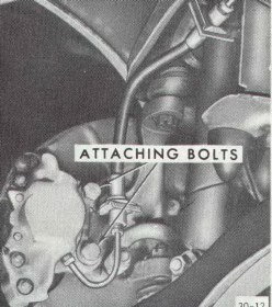
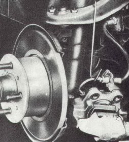
3. Remove two (2) bolts holding caliper to steering knuckle. See Figure 30-17. Hang caliper on a wire from the upper control arm as shown in Figure 30-18.
Figure 30-17 Caliper Attachment
|
Figure 30-18 Caliper hung by wire
|
|
|
|
4. Remove spindle grease cap. Remove cotter pin and spindle nut. Remove wheel hub with disc.
5. Install J-21689 spring until 3 1/8" clearance is obtained between spring compressor and lower spring leaf.
6. Remove upper ball joint using tie rod remover, J-21687.
7. Remove shock absorber at lower attachment only.
8. Remove lower ball joint using J-21687 remover and remove steering knuckle. Remove dust shield from steering knuckle.
c. Installation (Drum Brakes)
NOTE: Fasteners in subparagraphs b are important attaching parts in that they could affect the performance of vital components and systems, and/or could result in major repair expense. They must be replaced with one of the same part number or with an equivalent part if replacement becomes necessary. Do not use a replacement part or lesser quality or substitute design. Torque values must be used as specified during reassembly to assure proper retention of these parts.
1. Install lower ball joint in steering knuckle. Torque castle nut to 40 lb. ft. Install new cotter pin.
2. Attach shock absorber at lower end. Retorque bolt to 30 lb. ft.
3. Install upper ball joint in steering knuckle. Torque castle nut to 29 lb. ft. Install new cotter pin.
4. Remove spring compressor.
5. Install backing plate on steering knuckle and torque to specifications.
NOTE: Hex head bolt M10 torque to 47 lb. ft. Hex head bolt M8 torque to 18 lb. ft.
6. Install front wheel, hub and drum assembly on spindle and tighten spindle nut as stated in 31.2.
7. Install spindle grease cap and then hub cap.
d. Installation (Disc Brakes)
NOTE: Fasteners in subparagraphs b are important attaching parts in that they could affect the performance of vital components and systems, and/or could result in major repair expense. They must be replaced with one of the same part number or with an equivalent part if replacement becomes necessary. Do not use a replacement part or lesser quality or substitute design. Torque values must be used as specified during reassembly to assure proper retention of these parts.
1. Always replace paper gasket when installing dust shield on steering knuckle. Lightly coat both surfaces of paper gasket with chassis lubricant before installation and torque attaching bolts to 47 lb. ft.
2. Install lower ball joint in steering knuckle. Torque castle nut to 40 lb. ft. Install new cotter pin.
3. Attach shock absorber at lower end. Torque bolts to 30 lb. ft.
4. Install upper ball joint. Torque castle nut to 29 lb. ft. Install new cotter pin.
5. Remove spring compressor.
6. Install hub and disc on spindle and tighten spindle nut as stated in paragraph 31.2.
7. Install caliper on steering knuckle and torque bolts. See Figure 30-17.
8. Install wheel and torque wheel nuts to 65 lb. ft.
|