GT Heater System (Page 2)
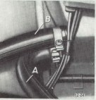
2. Detach coolant feed (A) and return (B) hoses, in engine compartment from heater core. See Figure 12-24.
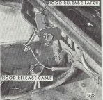
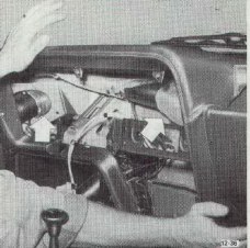
3. In engine compartment remove hood lock control cable retaining clip and cable from lock bar. See Figure 12-25.
4. Remove console shift over between seats using the following instructions:
a. Remove ash tray and remove 2 screws under it.
b. Remove retaining screws in headlamp lever handle and remove handle.
c. Console cover is held in place by four push button type studs, unsnap studs by prying up and work cover upwards over shift lever and rubber shift lever boot.
 Figure 12-24 Figure 12-24
|
Figure 12-25
|
Figure 12-26
|
|
|
|
|
Figure 12-27
|
Figure 12-28
|
Figure 12-29
|
|
|
|
|
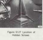
5. Remove left cover and right plug in instrument panel cover and through openings remove instrument panel attaching screws. See Figures 12-26 and 12-27
6. Remove two multiple wire plug connectors from steering column harness.
7. Detach speedo cable.
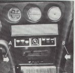
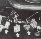
9. Below left side of instrument panel, disconnect five multiple wire plug connectors. See Figure 12-29.
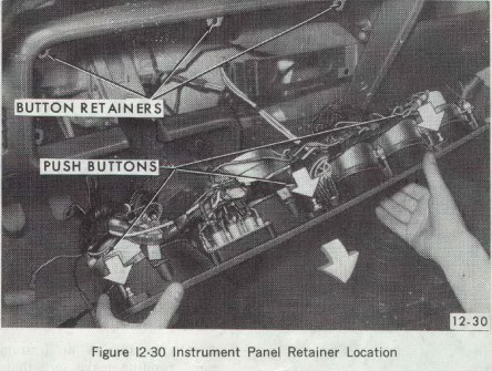
10. Remove two (2) sheet metal screws on either side of radio face and one (1)-retaining nut on lower left side of instrument housing. Remove the housing by pulling on topside of instrument panel to unsnap three (3) push button type retainers. See Figure 12-30 for location of two (2) sheet metal screws, retaining nut and three (3) push button retainers.
Figure 12-30
|
|
|
|
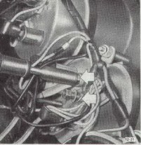
11. Mark electrical wire to ammeter and detach (on 1.9 liter S. Engine only). See Figure 12-31.
Figure 12-31
|
Figure 12-33
|
|
|
|
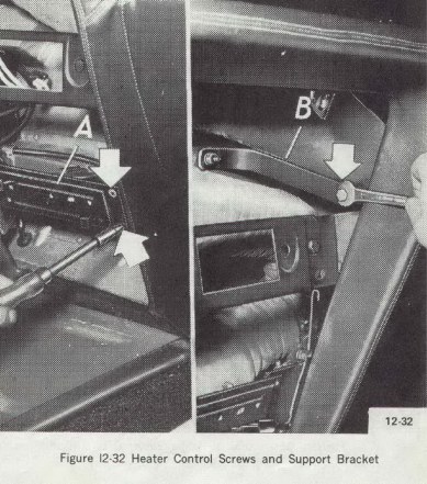
12. Unscrew heater controls (A) and support bracket (B). See Figure 12-32.
Figure 12-32
|
|
|
13. Disconnect heater and defroster duct hoses from instrument panel. See Figure 12-22.
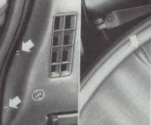
14. Remove all screws from instrument panel padding and remove it from instrument panel. The arrows in Figure 12-34 show the location at the left side of the dash panel and windshield. Screws are located in the same areas on the right side.
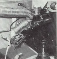
15. Remove one bolt at top of heater blower case and two nuts from bottom of the case and remove the heater blower and case assembly. See Figure 12-35.
Figure 12-34
|
Figure 12-35
|
|
|
|
16. On removed heater assembly, check the relative position of the mixed air door so that on installation of the unit the hand control levers can be positioned according the unit settings, either opened or close.
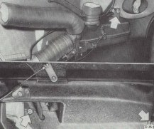
17. On installation of instrument panel padding make sure that air hoses are properly positioned and connected. See Figure 12-36.
18. Install heater assembly by reversing the removal procedures.
Figure 12-36
|
|
|
12-30 Defroster Jet Removal and Installation
1. Remove instrument panel cover assembly. Refer to Group 120.
2. Remove screws securing jet to cover assembly.
3. Install reverse of removal procedure.
12-31 Heater Valve
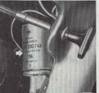
The heater valve on the 1970 Opel GT has been moved to the engine compartment, the same as the Kadett models, this was done for easier service. The valve will be removed using the same procedures used to remove the heater valve on the Kadett's. See Figure 12-37 for the location.
Figure 12-37
|
|
|
DIVISION IV
TROUBLE DIAGNOSIS
12-32 Heater System Trouble Diagnosis
Trouble
The temperature of the heated air at the outlets is too low.
Cause and Correction
Check radiator cap for proper sealing action - replace if necessary.
Check for adequate coolant supply. If level is down, correct cause of coolant loss and refill radiator.
Inspect hose for kinks - relieve kinks or replace hoses.
Check thermostat operation by measuring temperature of coolant at radiator. Temperature should be within 5 degrees F. of thermostat rated value.
Check that air doors and water temperature control valve are operating properly.
Check for plugged heater core - backflush heater core as necessary.
Trouble
Inadequate defrosting action.
Cause and Correction
Examine heater-defroster door for proper operations - adjust Bowden Cable as necessary.
Check that air hoses connecting to defroster outlets are secure.
Check for air leaks around edges of heater air distributor housing - seal leaks as necessary with body sealer. Check for body air leaks and seal as necessary with body sealer.
Trouble
Blower inoperative
Cause and Correction
Check the blower fuse - replace if necessary.
Check wiring for open circuit - correct as required.
Inspect for defective component (i.e., blower switch or blower motor) - replace or repair as necessary.
|