Rear Suspension
DESCRIPTION AND OPERATION
The Opel Kadett and GT both utilize the three-link rear suspension arrangement. This rear suspension consists of coil springs, track rod, shock absorbers and lower control arms.
The coil springs set between two seats, which are situated ahead of the rear axle housing.
The track rod is utilized on all models to control the lateral stability of the rear axle assembly. It is of tubular design. A stabilizer rod is used on all wagons as well as fastbacks and sedans equipped with a 1.9 engine. The GT is not equipped with a stabilizer rod.
The lower control arms are of tubular design and function as two links of the three-link suspension system. They are attached to the underbody through brackets welded to the side rails and to the rear axle assembly through the front portion of the spring seat bracket. The lower control arms control the fore and aft movement of the rear axle assembly.
The third link in this suspension system is the torque tube, which is connected to the differential carrier and also to the underbody through rubber bushings in the central joint support bracket.
The torque tube in conjunction with the lower control arms absorbs all acceleration and braking torque.
DIVISION III
Service Procedures
 40-1 Rear Shock Absorber Removal and Installation 40-1 Rear Shock Absorber Removal and Installation
a. Removal
1. Remove upper attaching nut, retainer and rubber grommet.
2. Remove lower attaching nut and rubber grommet retainer, compress shock absorber and remove from lower mounting pin.
b. Installation
1. Replace upper and lower rubber grommets, if necessary, before installing shock absorber.
2. Extend shock absorber and position in car. Attach at lower end first, torque nut to 15 lb. ft.
3. Install rubber grommet, retainer and self-locking nut at top of shock absorber. Torque to 10 lb. ft.
NOTE: Always use new self-locking nuts.
40-2 Rear Spring Removal and Installation
a. Rear Spring Removal
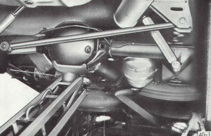
Figure 40-1 Raising Rear of Car
|
|
|
1. Raise rear of car with floor jack under differential carrier and support with jack stands positioned under side jack brackets. See Figure 40-1.
2. Remove rear wheels.
3. Disconnect shock absorbers from the rear axle.
4. Disconnect stabilizer, shackles, if equipped from rear axle brackets.
NOTE: It isn't necessary to disconnect the track rod.
5. Lower rear axle assembly as far as possible without putting the brake hoses under stress.
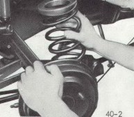
6. If necessary, tilt the rear axle assembly to remove the springs. See Figure 40-2. Note the upper and lower rubber damper rings.
Figure 40-2 Removing Coil Spring
|
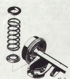
Figure 40-3 Installing Coil Spring
|
|
|
|
b. Rear Spring Installation
1. Make certain the lower damper rings are properly positioned in the spring seats and position the springs in their respective position in the damper rings. See Figure 40-3.
2. Properly install upper damper rings on springs.
3. Raise the rear axle assembly to compress springs in their seats.
4. Attach shock absorbers and tighten retaining nuts to 15 lb. ft.
5. Attach stabilizer shackles, if equipped, to axle brackets and tighten bolts to 25 lb. ft. with vehicle at curb weight.
6. Install rear wheels. Torque lug nuts to 65 lb. ft.
7. Remove jack stands.
40-3 Lower Control Arm Replacement
This operation can be performed with the vehicle standing at curb height or elevated.
1. Disconnect the parking brake cable from support bracket on control arm.
2. Loosen and remove front and rear control arm attaching bolts and remove the control arm.
3. Reverse the above procedures for installation of the control arms.
4. On Kadett's, place a load of approximately 350 lbs. In luggage compartment, or on the GT, place a load of approximately 150 lbs. On the driver's seat and Torque the control arm attaching bolts and nuts to 18 lb. ft.
Note: This front lower control arm ball joint to steering knuckle fastener is an important attaching part in that it could affect the performance of vital components and systems, and/or could result in major repair expense. It must be replaced with one of the same part number or with and equivalent part if replacement becomes necessary. Do not use a replacement part of lessor quality or substitute design. Torque values must be used as specified during reassembly to ensure proper retention of this part.
40-4 Stabilizer Rod Replacement
a. Removal
1. Raise and support the rear of the vehicle.
2. Release muffler and tail pipe rubber retaining rings.
3. Disconnect stabilizer rod to shackle bolts.
4. Disconnect stabilizer rod to underbody retainers and work stabilizer rod out from under the vehicle.
b. Installation
1. Work stabilizer rod into position and loosely attach stabilizer to underbody retainers.
2. Connect stabilizer rod to shackles.
3. With the vehicle standing on its wheels or the rear axle assembly lifted, tighten stabilizer rod to underbody bracket bolts to 15 lb. ft.
4. Install muffler and tailpipe retaining rings.
5. Remove the jack stands and lower the vehicle.
40-5 Track Rod Replacement
a. Removal
1. Lift the rear of the car and suitably support.
2. Disconnect track rod from rear axle and side member
b. Installation
1. Loosely connect track rod first to side member and then to the rear axle.
2. On Kadett's, place a load of approximately 350 lbs. In luggage compartment, or on the GT, place a load of approximately 150 lbs. On the driver's seat and tighten track rod attaching bolts to 40 lb. ft.
Figure 40-4 Exploded View - 1.1 Rear Suspension
|
|
|
Figure 40-5 Exploded View - 1.9 Rear Suspension
|
|
|
|