Kadett Heater System
 12-1 SPECIFICATIONS 12-1 SPECIFICATIONS
|
ENGINE
|
|
1.1 Liter
|
1.9 Liter
|
Recommended Coolant
|
Ethylene-Glycol Base
|
Thermostat Opens at (degrees)
|
189
|
189
|
Cooling system capacity (with heater)
|
5 ½ qt.
|
6 qt.
|
Blower Motor Type
|
12 VDC
|
Blower Fan Type
|
Blade
|
DIVISION I
12-2 Control Cable Adjustment
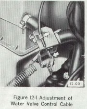
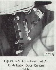
The adjustment of the control cables is accomplished by the positioning of the jacket or sheath, (as held by the clamps).
To adjust control cables, loosen the clamps and move the cable sheath in or out to obtain full travel of lever on water valve to air distributor door. See Figure 12-1 or 12-2.
Figure 12-1
|
Figure 12-2
|
|
|
|
DIVISION II
Description and Operation
12-3 Flow-Through Ventilation System Description and Operation
A separate ventilation system for direct intake of outside air is controlled by two rotary breakaway plastic fresh air inlet nozzles in the instrument panel on all models. Pushing the turn plate at the triangular symbol permits the entrance of outside air through the respective left or right side inlet. When open, the turn plate can be rotated to direct airflow in the desired direction. See Figure 12-5.
Flow-through ventilation is used on the Fast Back Series. For the Model 91 Two-Door Fast Back Sport Sedan, air outlets will be on both sides of the back glass. On the Model 92 Rallye and the Model 95 Two-Door Fast Back Coupe, the air outlets will be through the water channel of the trunk lid opening.
On the Model 31 Two-Door Sedan and the Model 39 Station Wagon, there will be no air outlets in the rear. For adequate flow-through type ventilation, it will be necessary to open the hinged rear quarter windows.
12-4 Heater System Description
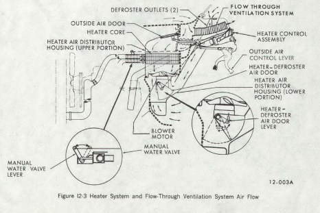
Figure 12-3
|
|
|
The Opel Kadett heater system consists of four components: (1) heater core, (2) manual water valve, (3) heater air distributor housing, and (4) heater control assembly. The flow of air enters the car through the cowl; passes through the outside air inlet, heater core, and then enters the lower portion of the heater air distributor housing located under the instrument panel. See Figure 12-3.
The heater-defroster air door directs the air to the floor outlets, defroster jets, or to both outlets depending on the position of the door. A manual water valve regulates the flow of coolant through the heater core, thereby varying the temperature of the airflow past the core. The blower motor is located on the lower portion of the heater distributor housing.
Opening and closing of the heater defroster door and manual water valve is accomplished by Bowden Cables connected to the heater control. The heater controls function as follows:
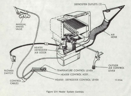
Heater-Defroster Control Lever - This lever opens and closes heater-defroster air door which channels the air flow to either the lower heater outlets or to defroster jets, or to both outlets simultaneously, depending on the position of the control. See Figure 12-4.
Figure 12-4
|
|
|
Temperature Control Lever - This lever regulates the flow of coolant through the heater core and thereby increases or decreases the air temperature proportionate to its travel, (toward red dot - warm; toward O - off).
NOTE: Unheated air may be circulated through the car by leaving the temperature control in the off position and the outside air door open, (outside air control lever pushed forward).
Blower Switch - This control actuates blower motor to low or high blower speed.
Outside Air Control Lever - This lever opens the outside air inlet door, permitting air to enter the system. Pushing outside air control lever forward, (towards engine), opens outside air inlet door. The first position allows a small amount of air to enter, and the second position allows full open - creating a greater airflow. The lever must be in one of the open positions in order for the heater to operate properly and efficiently. The outside air inlet door can be closed by pulling lever rearward.
12-5 Heater System Operation
To operate heater proceed as follows:
1. Push outside air inlet control lever forward.
2. Position heater-defroster control lever, (bottom lever) as desired.
a. Left position air flows to windshield,
b. Right position air flows to floor.
By moving the lever between left and right position, the airflow can be regulated to either windshield or floor.
3. Position temperature control lever, (top lever) as desired to increase or decrease temperature of airflow, (position lever to left for heat).
4. Position blower switch as desired to operate blower at low or high speed.
DIVISION III
Service Procedures
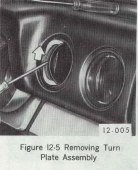
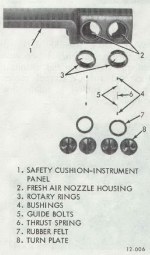
12-6 Fresh Air Nozzle Turn Plate and Rotary Ring Removal and Installation
a. Removal
1. Pull rubber felt partially to of turn plate assembly. See Figure 12-5.
2. Using a small screwdriver, carefully pry turn plate apart and remove both halves and rubber felt.
3. Compress the thrust spring and remove thrust bolts, and bushings.
4. Pull rotary ring out of fresh air nozzle housing.
Figure 12-5
|
Figure 12-6
|
Figure 12-7
|
|
|
|
|
b. Installation
1. Place rubber felt on one half of turn plate and press two halves of turn plate assembly together.
2. Place assembled turn plate inside rotary ring.
3. Align holes in rotary ring and turn plate assembly.
4. Insert one bushing into rotary ring and turn plate assembly.
5. Insert second bushing into rotary ring and turn plate assembly, being careful to assemble both bushings on the same side of rubber felt.
6. Insert the guide bolt, thrust spring and second guide bolt into rotary ring and turn plate assembly.
7. Insert rotary ring and turn plate assembly into fresh air nozzle housing.
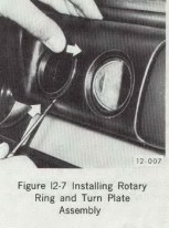
8. Using a small screwdriver, press one guide bolt flush with surface of rotary ring and push that side of rotary ring into place. Do the same to the other guide bolt. See Figure 12-7.
9. Check the rotary ring and turn plate assembly for smooth operation.
|