Windshield Wipers (page 2)
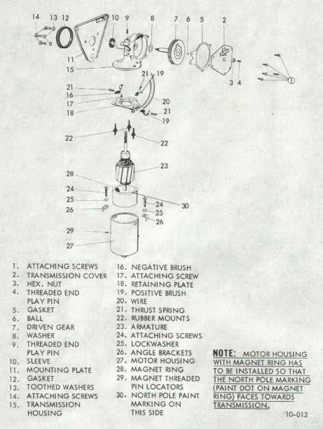
 10-8 Cleaning and Inspection of Parts 10-8 Cleaning and Inspection of Parts
With the exception of electrical parts and bushes, clean all components in a cleaning solvent. See Figure 10-17.
Figure 10-17
|
|
|
1. Check armature windings for ground, or open circuit. If a ground or open circuit is evident, the armature must be replaced. If the armature checks out, the commutator can be undercut.
2. Check brush springs. Spring pressure of new brushes should be 6.35 to 8.47 ounces. Spring pressure of worn brushes should be at least 3.5 ounces. In case of lower spring pressure, replace springs.
3. Check brushes for wear and replace if necessary. Minimum brush length should be .24 inch.
4. Check driven gear for wear and replace if necessary.
10-9 Assembly of Wiper Motor
1. Fill transmission (driven gear) housing with 1/8 inch layer of grease meeting GM Specifications 02383).
2. Install driven gear into housing.
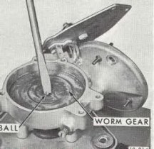
3. Apply a small amount of grease to ball cavity of driven gear and insert ball. See Figure 10-18.
.
Figure 10-18
|
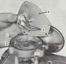
Figure 10-19
|
|
|
|
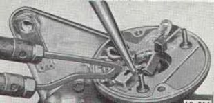
5. Solder positive brush lead(s) to brush holder(s). Hold brush leads with needle nose pliers to prevent solder from running up wire strands. See Figure 10-20.
Figure 10-20
|
|
|
7. Apply a small amount of grease to end of armature shaft. Lightly oil armature shaft.
8. Insert brush springs and brushes into brush holders. Carefully slide armature into housing.
NOTE: Take care not to damage brushes when installing armature.
9. Install motor housing over armature so that large drain hole on housing is facing downward when motor assembly is installed in car. Insert angle brackets into motor housing and tighten attaching screws.
NOTE: Be sure to reseal angle brackets to motor housing after retaining screws are tightened.
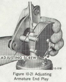
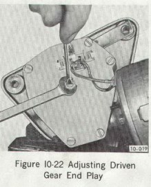
10. Connect assembled motor with an ammeter and adjust endplay of armature shaft and drive gear. To do so, turn in the respective adjusting screw until the current consumption increases. Then back off adjusting screw ½ turn. Secure driven gear adjusting screw with lock nut and armature adjusting screw with paint. See Figures 10-21 and 10-22.
Figure 10-21
|
Figure 10-22
|
|
|
|
10-10 Removal and Installation of Windshield Wiper Switch
a. Preliminary inspection
1. Remove two access hole covers, one on each side of the forward part of the console.
2. Through access holes, remove two instrument housing attaching screws.
3. Lower steering column from instrument panel.
4. Disconnect upper end of speedometer cable.
5. Pull or carefully pry instrument housing from instrument panel. Housing is retained across the top by snap clips.
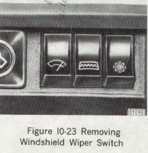
6. Pull out and rotate instrument housing for access to back of wiper switch. See Figure 10-23.
Figure 10-23
|
|
|
b. Checking Wiper Operation
1. Turn ignition switch on and engage wiper switch to see if wiper motor will operate.
2. If wiper action is slow or inoperative, turn switches off and detach wiper control arm from crank arm.
3. Operate wiper manually checking for excessive bind in linkage. Correct if necessary.
4. Turn switch on to see if wiper motor will function with wiper linkage detached. If wiper motor will not run, disconnect connector at wiper motor and connect hot lead from battery to terminal N,. 53 on wiper motor. If wiper motor runs, the wiper switch is faulty or there is a break in the lead wire. If wiper motor still will not run, remove and bench test
|