Front Suspension
DIVISION I - Specifications and Adjustments
30-1 Front Suspension Specifications (see below)
a. Torque Specifications
Use a reliable torque wrench to tighten all parts listed, to insure proper tightness without straining or distorting parts. These specifications are for clean and lightly lubricated threads only; dry or dirty threads produce increased friction, which prevents accurate measurement of tightness.
DIVISION II
Description and Operation
 30-3 Suspension Description 30-3 Suspension Description
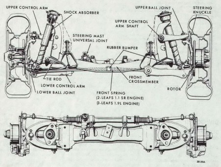
The Opel Kadett and Opel GT use maintenance free independent front wheel suspension and feature unequal length control arms and a transverse two-leaf spring for models equipped with 1.1 liter engines and three-leaf spring on those models with 1.9 liter engine. The GT uses the three-leaf spring for both engines. The entire front suspension is attached to the front cross member and can be removed as a unit if so desired.
The engines installed in the GT are not supported by mounting brackets, but rest on a separate cross member. The front suspension cross member for both engines is reinforced in the area of the attachment to the frame. A one part damper plate is installed between cross member and frame.
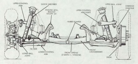
Figure 30-1 Kadett Front Suspension (Drum Brakes)
|
|
|
Figure 30-2 GT Front Suspension (Disc Brakes)
|
|
|
Ball joints are employed in the conventional manner to provide pivoting joints between the control arms and steering knuckles. Two large rubber bumpers attached to the cross member limit upward movement of the control arms.
The double direct acting shock absorber and a transverse double or triple steel band spring dampens road shock. In addition, the shock absorber limits downward travel of the control arms.
All moving parts, including ball joints, have no need for lubrication or have been pre-lubricated for the life of the vehicle.
For distinguishing the individual cross members, a red label with black letters is stuck onto the front side of the shock absorber support.
The individual front suspension designs, their markings and appropriate front springs and shock absorbers are indicated in the table in Figure 30-4.
DIVISION III
SERVICE PROCEDURES
30-4 Removal and Installation of Front Suspension (Complete Assembly)
a. Removal (Kadett and GT)
1. Prior to raising front end of car, apply parking brake and block rear wheels.
2. Raise front end of car with a jack. It is recommended that a wood block be placed between the jack and the front cross member to prevent damage to the cross member.
3. Support front end of car by placing floor stands under jacking brackets.
4. Support 1.1 engine-transmission assembly in uppermost position with jack stand at rear of engine.
The 1.9 engine and transmission assembly can be supported in this manner or and alternate method would be to use Engine Holding Fixture, Tool J-23098 for the Kadett and Tool J-23375 for the GT. See Figure 30-5.
Figure 30-5 Engine Holding Fixture Installed
|
|
|
Install tool be removing upper engine mount nut and installing fixture. Replace nuts and tighten. The tool between the frame rails will now support the engine.
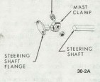
5. (Kadett) Remove steering mast clamp bolt. Mark locations of shaft to flange. See Figure 30-6.
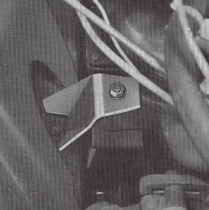
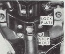
6. Remove steering mast guide sleeve stop bolt from mast jacket bracket. See Figure 30-7. Pull steering column out of steering mast flange.
CAUTION: Avoid any shock or blows onto the steering mast, as all elements of the energy absorbing columns are sensitive to damage and must be HANDLED WITH CARE.
Figure 30-6
|
Figure 30-7
|
Figure 30-8
|
|
|
|
|
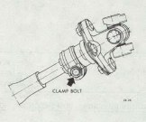
6a. (GT) Loosen steering mast at the lower universal joint and take out clamp bolt. Loosen clamp at the upper universal joint and lift steering mast upwards until it is free at the lower universal joint. See Figure 30-8.
7. Disconnect brake lines at brake hose.
8. Disconnect shock absorber mountings at upper shock mounting bolts. It is necessary to remove air cleaner on all GT models. See Figure 30-19.
9. (GT) Unscrew radiator from support on cross member.
10. Remove engine-mounting nuts.
11. Remove front suspension cross member attaching nuts and lower the cross member.
b. Installation
NOTE: Fasteners in subparagraph b are important attaching parts in that they could affect the performance of vital components and systems, and/or could result in major repair expense. They must be replaced with one of the same part number or with an equivalent part if replacement becomes necessary. Do not use a replacement part of lesser quality or substitute design. Torque values must be used as specified during reassembly to assure proper retention of these parts.
1. Support front suspension and cross member on jack and raise into position.
2. Attach cross member to front frame rail. Torque to 36 lb. Ft.
3. Install engine-mounting nuts. Remove engine support.
4. Install shock absorber mounting bolts. Install air cleaner on GT models.
5. Connect brake hoses and bleed brakes as outlined in Group 50.
6. (GT) Install radiator mounting bolt in support cross member.
7. Push steering column downwards until a 1/8" clearance is obtained between steering wheel hub and switch cover.
8. (Kadett) With steering wheel in centered position and front wheels straight ahead, tighten the steering mast clamp bolt under the car and torque to 15 lb. Ft. See Figure 30-6.
8a. (GT) With steering wheel in centered position and front wheels straight ahead, tighten the clamp bolt at the lower universal joint to 22 lb. Ft. and the clamp at the upper universal joint to 14 lbs. Ft. See Figure 30-8.
9. Install mast guide sleeve stop bolt.
10. Remove front support stands and lower vehicle.
|