Opel GT

For the Opel GT Enthusiast!


Additional navigational links
are available at the bottom
of this page.


Front Suspension (page 2)
   
8a. (GT) With steering wheel in centered position and front wheels straight ahead, tighten the clamp bolt at the lower universal joint to 22 lb. Ft. and the clamp at the upper universal joint to 14 lbs. Ft. See Figure 30-8.

9. Install mast guide sleeve stop bolt.

NOTE: Always install new lock plate. See Figure 30-7.

10. Remove front support stands and lower vehicle.

 30-5 FRONT WHEEL ALIGNMENT

Wheel alignment is the mechanics of adjusting the position of the front wheels in order to attain the least steering effort with a minimal amount of tire wear.Correct alignment of the chassis is essential to proper alignment of the front and rear wheels. Briefly, the essentials are that the frame must be square in within specified limits. The top and bottom surfaces of the front cross member must be parallel fore and aft, and that the upper and lower control arm must be at correct location in respect to shafts and the front cross member. All bushings, ball joints and bolts must be of proper torque and in usable condition. Wheel and tire balance has an important effect on steering and tire wear. If wheels and tires are out of balance, "shimmy" may develop or tires may wear unevenly and fire the erroneous impression that the wheels are not in proper alignment. For this reason, the wheel and tire assemblies should be known to be in proper balance before assuming that wheels are out of alignment. Close limits on caster, front wheel camber, and theoretical kingpin inclination are beneficial to car handling, but require only reasonable accuracy to provide normal tire life. With the type of front suspension used, the toe-in adjustment is much more important than caster and camber are as far as tire wear is concerned.

Caster and camber adjustments need not be considered unless visual inspection shows these settings to be out, or unless the car gives poor handling on the road. In majority of cases, services consisting of inflating tires to specified pressure and interchanging tires at recommended intervals, balancing all wheels and tires, adjusting steering gear and setting toe-in correctly will provide more improvement in handling and tire wear than will front end alignment adjustments.

The correct use of accurate front-end alignment equipment is essential to determine whether shock or accident has damaged front suspension parts, and to obtain settings after new parts have been installed.

a. Inspection Before Checking Front Wheel Alignment

Before making any adjustment affecting caster, camber, toe-in, theoretical kingpin inclination, or steering geometry, the following checks and inspections must be made to insure correctness of alignment equipment readings and alignment adjustments.

1. The front tires should have approximately the same wear and all tires must be inflated to specified pressures, (paragraph 100-1).

2. Check front wheel bearings for looseness and adjust if necessary, (paragraph 100-4).

3. Check for run-out of wheels and tires.

4. Check wheels and tires for balance and correct if out-of-balance, (paragraph 100-3).

5. Check for looseness at ball joints and tie rod ends; if found excessive it must be corrected before alignment readings will have any value.

6. Check shock absorber action and correct if necessary.

CAUTION: Consideration must be given to optional equipment on the car, undercoating, dirt, etc.

7. It is advisable to check the condition and accuracy of any equipment being used to check front-end alignment and to make certain that instructions of the manufacturer are thoroughly understood.

b. Adjusting Caster

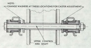
To change caster, three washers are available - one with a .12" thickness, one that is .36" thick and one .24" thick. To increase caster place one of the thin washers at the front of the control arm shaft and one thick washer at the rear. To decrease caster place one of the thick washers at the front of the control arm shaft and one thin washer at the rear.

1. Position jack below front suspension cross member and raise front end of car.

2. A Place jack stands below front side members and remove front wheel on side which caster is to be adjusted.

3. Install front spring compressor J-21689 and compress spring. See Figure 30-9.

 Figure 30-9  J-21689 Installed
 Figure 30-10 Upper Control Arm Shaft and Bushings
4. Remove upper control arm shaft.

5. Remove upper control arm from shock absorber support, being careful not to lose toothed washers.

6. Adjust caster by installing selective toothed washers on both sides of control arm shaft, between control arm and shock absorber support.

NOTE: Never use ore than one washer at any one location. The total thickness, front and rear washer, must equal .48". There are only three possible caster changes that can be made.

7. Using a drift to align holes, replace control arm shaft in the direction as shown in Figure 30-10. Torque hex nut to 33 lb. Ft.

NOTE: Make certain that crown of both plate washers show inward.

8. Remove spring compressor, and install front wheel and torque wheel nuts to 65 ft. lbs.

9. Recheck caster.

c. Adjusting Camber

Camber is adjusted by turning the upper ball joint flange 180 degrees. This means that only two possible camber adjustments can =be made. At the factory, camber is set at the smallest possible positive camber setting. Rotating the flange will make camber more positive.

1. Raise front end of car using block of wood on jack to prevent damage to the front cross member.

2. Support car below left and right front spring eye on lower control arm and remove front wheel on side to be adjusted.

3. Remove ball joint from upper control arm and front steering knuckle.

4. Lift upper control arm and turn the ball joint flange through 180 degrees.

5. First tighten both ball joint attaching bolts on upper control arm and then the ball stud castle nut. Torque to 29 ft. lbs. Install new cotter pin.

6. Install front wheel and torque wheel nuts to 65 feet.

7. Recheck camber.

d. Adjusting Toe-In

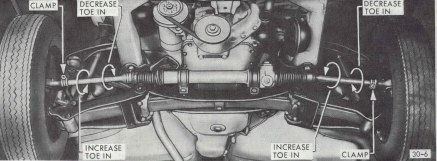
Toe-in is adjusted b rotating the tie rod sleeves. Refer to Figure 30-11.

 Figure 30-11 Adjusting Toe-in
1. Recheck caster and camber before proceeding with toe-in adjustment. If correct, adjust toe-in.

2. Set wormshaft and ball nut to steering wheel half way from one stop to the other, noticing the following:

  (a) With the steering wheel hub button removed, the marking on the steering shaft end should be in a horizontal position.

  (b) The steering wheel spokes should also be in a centered position.

3.  Remove wire clamps on left and right tie rod and push back bellows.

4. Loosen clamp bolts and tie rods. See Figure 30-11.

5. The toe-in should be 1/32" - 1/8".

NOTE: When adjusting toe-in, never grip tie rod on inner ball stud joint. To avoid ball stud resting against inside of hole in tie rod outer end, center outer end of each tie rod to the ball stud.

6. Pull bellows over tie rods and attach with wire clamps. The bellows must not be twisted and wire ends must show towards steering gear adjusting screw opening.

7. Torque clamp bolts to 12 lb. Ft.

8. After toe-in adjustment, turn steering wheel several times completely towards the left and right to determine whether bellows are properly attached to the tie rods and steering gear housing.

e. Checking Theoretical King Pin Inclination

CAUTION: When checking theoretical king pin inclination, car must be on a level surface, both transversely and fore and aft, trim heights must be within limits, and the car must be at curb load.

With camber known to be within specified limits, theoretical kingpin inclination should check within specified limits.

If camber is incorrect beyond limits of adjustment and theoretical kingpin inclination is correct, or nearly so, a bent steering knuckle is indicated.

There is no adjustment for theoretical kingpin inclination as this factor depends on the accuracy of the front suspension parts. Distorted parts should be replaced with new parts.

CAUTION: The practice of heating and bending front suspension parts to correct errors must be avoided as this may produce soft spots in the metal in which fatigue and breakage may develop in service.

 30-6 FRONT WHEEL BEARING ADJUSTMENT

1. If wheel has not previously been removed front the car, remove grease cap, cotter pin and spindle nut. Discard cotter pin.

2. Torque spindle nut to 18 lb. Ft. while rotating wheel. This will allow for the bearings to settle.

3. Back of steering knuckle nut ¼ turn. If slot and cotter pin hole are staggered, further back off nut ½ turn, but do not tighten, until net hole in nut is in alignment with hole in spindle. Install new cotter pin.

NOTE: A properly adjusted wheel bearing has a small amount of endplay and a loose nut when adjusted in the above manner.

 30-7 UPPER BALL JOINT REMOVAL AND INSTALLATION

a. Removal

1. Place jack under spring eye and raise car. Remove front wheels from car.

2. Remove cotter pin and castle nut from upper ball joint stud. Discard cotter pin.

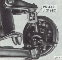
3. Press ball stud from steering knuckle using puller J-21687, and remove two (2) bolts attaching ball joint to upper control arm. See Figure 30-12.

4. If dust cap on upper ball joint is torn or missing, the ball joint should be replaced.

 Figure 30-12 Upper Ball Joint
 Figure 30-13 Lower Ball Joint
b. Installation

1. Install upper control arm ball joint with off center holes in flange showing towards the steering knuckle spindle.

2. Install tow (2) bolts attaching ball joint to upper control arm. Torque nuts to 16 lb. ft.

3. Install upper ball joint stud in steering knuckle and torque castle nut to 29 lb. Ft.

4. Install new cotter pin and replace wheels.

5. Always check caster and camber after installing new ball joints.

 30-8 LOWER BALL JOINT REMOVAL AND INSTALLATION

New lower ball joints have an axial play of up to .020 inch. The maximum permissible axial play of older ball joints is .080 inch. At an axial play of more then .080 inch, the lower ball joint must be replaced. If dust cap on upper ball joint is torn or missing, the ball joint should be replaced. See Figure 30-13.

a. Removal

1. Raise car and support at rear of front frame rails.

2. Remove front wheel.

3. Remove cotter pin from castle nut on ball joint stud and back off castle nut two (2) turns. Hit ball stud a sharp blow to break it loose. DO NOT REMOVE NUT.

4. Install spring compressor J-21689 and compress spring until a distance of 3 1/8" is achieved between spring compressor and lower spring leaf. See Figure 30-9.

5. Disconnect shock absorber to lower control arm attachment bolt and swing shock absorber out of the way.

6. Remove castle nut from ball joint stud.

NOTE: Prior to the removal of the lower ball joint from the control arm, not the position of the locating notch shown in Figure 30-14, in the rim of the ball joint housing. Scribe or mark the control arm to facilitate alignment of the replacement ball joint during installation.

7. Pry off dust cap retainer and remove dust cap being careful not to damage it.

8. Press ball stud out of lower control arm.

b. Installation

1. When pressing the ball joint in place, make certain the locating notch in the lower rim of the ball joint matches the alignment reference make placed on the lower control arm prior to removal. The notch in the ball joint bottom plate identifying the direction of the elongated slot must point towards the brake drum backing plate. See Figure 30-14. Alignment must be within 2 degrees of lower control arm centerline.

 Figure 30-14  Lower Ball Joint Notch
CAUTION: If proper positioning of the ball joint is not accomplished, the result is a limitation of the necessary ball stud movement. If ball stud movement is limited, and interference between the ball stud and housing is created, and binding or even fracture may occur. When pressing in ball joint do not press on bottom plate, but on ball joint housing only.

2. Install dust cap on lower ball joint and fill with chassis lubricant. Attach dust cap retainer.

3. Press ball joint into steering knuckle. Use J-9519-3 as installer and J-21690 as a supporting sleeve.

4. Install castle nut on ball joint stud and torque to 40 lb. Ft. Install new cotter pin.

5. Reconnect shock absorber to the lower control arm and torque to 30 lb. ft.

6. Remove spring compressor.

7. Install front wheels and lower the car.

8. Always check caster and camber after ball joint replacement.


Site Created: July 5th, 2000     Creator of Site: Tim Doyon, Oklahoma City, OK